We're pretty much used to the new engine now. The last long trip to Ohio went well, with the van roaring up the interstate hills here at 65 - 70 mph. Just don't let the speed drop below 60, though, since it falls off the torque curve and then the speed drops until you have to downshift.
Fuel mileage has improved from 21 - 23 to almost 26, which is a welcome improvement as we near $4 gallon for regular gas.
Strangely, the end of the oil dipstick broke off at the top hole drilled into it for oil measurement. Why they drilled holes, in addition to stamping the measurement points into the blade, I don't know. A new dipstick (with the same holes) was $18, and I hope to find the end of the dipstick in the bottom of the oil pan when I change the oil shortly.
Coolant needed to be added for several weeks after launch, since the system appears to take awhile to purge itself. It's been a month now without needing any, so that's fine, though I still need to bite the bullet and fix the leaking heater shutoff valve. It will soon be too warm to ignore it.
Wednesday, May 9, 2012
Friday, March 16, 2012
Latest Update
The engine is still running pretty smoothly, though it has had two hard-to-start-when-hot incidents. We filled the gas tank for the first time earlier this week, and I added a dose of Techron fuel system cleaner in case we still have any sticky injectors. I plan to try to run the MAF-cleaning test this weekend. No matter the outcome, we're hoping to take the vanagon on a round-trip 600-mile run on Monday/Tuesday, but we may change our mind, because the weather has been beautiful late spring temperatures, and the motorcycle beckons.
I'm afraid there's a small leak in the rear heater core. After trying to extract the heater core during the last round of cooling system connecting, I found, via a stepwise disassembly, that you must remove its cover, then remove the front skirtboard, then pull up the rug and padding, then finally find out that you can't actually remove anything more unless you remove the entire rear seat and its support structure. So, I threw in the towel and put everything back together, after blotting up the tiny bit of coolant that I found underneath the heater. However, it still smells whenever we turn it on. Unless the leakage increases to a noticeable amount we'll live with it. I've seen on another site that other users have complained of this component developing leaks in its core.
Speaking of heaters, we've had a problem completely turning off the front heater. No matter how hard one shuts off the temp lever, the air blows out slightly warm once the engine warms up. My suspicion is that I've hooked the heater flow backwards, so that the hot water doesn't hit the cutoff valve until it passes through the heater core, instead of vice-versa, and that some small amount of hot coolant fills the heater core when this is the case. There's also an audible gurgling, when the van is stopped after driving awhile, that I think may be related to this. The connections are easy to reach, but I'm mulling over ways of switching the hoses without spilling a lot of coolant in the process. It's easy to pinch-clamp the hoses, but the connectors plumbed into the main coolant lines will need to be corked or something. Until I fix this, if we drive the van on the long trip and don't need the heat, I'm going to clamp the heater hose off at the engine, so that NO hot coolant reaches the heaters. Lazy but effective (as long as we don't need to defog the windshield).
Thursday, March 8, 2012
Stalling resolution, part one
The stalling fixed itself. On a test run to Lewisburg and the bank, the van coughed and stumbled into the drive-in line, idled fine for the several minutes it took to make a deposit, then I took off for home, ready to catch the engine at every stop. No problem at all, the rpm dropped but held at about 800 - 1000 for every stop. So I've put away the problem, but am pondering what could fix itself in this scenario.
My hypothesis originates with experience with our V70, which also has a MAF. For years, it was occasionally stalling at stops. Complaints to the dealer were useless, since it would never stall while they had the car, and there were no error codes in the computer. However, as part of the Great Power Steering Pump Debacle, we had taken it to AutoScandia in Herndon, Virginia, and it coughed on them while they were test driving it. The technician said this indicated that the MAF needed to be cleaned, and did so. It's never stalled since.
As almost everyone who does this conversion will probably do, I purchased a used MAF. It did not come in a plastic bag; on the contrary, it was pretty dusty. A MAF error could cause this stalling, and the MAF can conceivably clean itself . I don't have information on this particular unit, but the platinum-wire MAFs used in the Volvo 240 series would heat the wire briefly after the engine shut off, to burn off any contaminants.
I plan to run an Elmscan log of the MAF output, the throttle position, and the fuel trims before and after a MAF cleaning, and see if there's an obvious difference. In general, though, I think that anyone buying a used MAF would be well advised to also get a can of cleaner (about $6) and follow the cleaning directions, which would be easy to do before installing the MAF. Another thing I wonder about is the possibility of plastic dust in the airbox from the modification process. I washed the box after I was done modifying it, but there's always the chance I missed something on the "clean" side of the air path.
Saturday, March 3, 2012
Stalling update
Well, it isn't the speed sensor. I jacked up the driver's side rear wheel, and spun it while watching the Elmscan. The MPH dial registers off the speed sensor and worked just fine. So, back to troubleshooting.
Friday, March 2, 2012
Life on the knoll
Our farm is at elevation 2470 feet, on a small knoll, facing a valley that points south-southwest. Most of our weather approaches from the west or southwest, gets funneled in the valley, then hits us hard, and it gets a bit windy sometimes. How windy, you ask?
Yes, that's eighty-five miles per hour, a peak recorded on Wednesday night at about 8 pm. The constant speed was around sixty mph for about half an hour.
This wind came out of the west. How could we tell?


A total of eight trees down in the pasture. Fortunately for us, the power line is on the west side of the trees, so it's been spared this and other windstorms' damage. We're never short of firewood. On the minus side, we now need to re-shingle our roof. Looking forward to talking with the insurance agent about that.
In all this chaos, the power went down a little before 8 pm. As I've done ever since I bought it, I brought out the generator, and got ready to start it up in the morning if the power was still out. And, as it's happened in the four times previous to this, the power came back on in the dead of morning. So, we still have a generator that we bought almost a year ago that has never been fueled up and started. I think of it as sort of a talisman that guards us against long term power outages.
 |
| The gust needle on our expensive but accurate Maximum(tm) anemometer |
This wind came out of the west. How could we tell?

That's the rope that held the bird feeder between the porch and a tree. It's aligned almost exactly west. Sunrise revealed the not-unexpected:

A total of eight trees down in the pasture. Fortunately for us, the power line is on the west side of the trees, so it's been spared this and other windstorms' damage. We're never short of firewood. On the minus side, we now need to re-shingle our roof. Looking forward to talking with the insurance agent about that.
In all this chaos, the power went down a little before 8 pm. As I've done ever since I bought it, I brought out the generator, and got ready to start it up in the morning if the power was still out. And, as it's happened in the four times previous to this, the power came back on in the dead of morning. So, we still have a generator that we bought almost a year ago that has never been fueled up and started. I think of it as sort of a talisman that guards us against long term power outages.
Latest news
The conversion had been running fine, with one exception: the shifting out of reverse is very difficult. Apparently, the extremely slight difference in the reinstalled transmission position, combined with the (now I know) extreme sensitivity of the adjustment of the linkage, is sufficient to cause a problem with the shifting. There is a fairly simple adjustment procedure in the Bentley manual, but it requires dropping the spare tire, again, and getting access to the bottom of the shifter (front) to allow proper adjustment. I think I'm going to try to fiddle with adjusting the clamp under the middle of the van, which is easy to reach, and see if I can find a sweet spot without so much work.
Second issue: if you bought the proper Ford engine mounts (much $$$), you saw in the SK-M kit instructions that Bostig recommends you check the clearance of the ring at their base and ensure there's enough clearance between the ring and the steel cradle. Well, when the engine is mounted, but hasn't sat with full weight, there's plenty of clearance. Once the engine hoist is removed, though, the rings apparently WILL contact the cradle. I need to remember to tell Bostig that there's no reason to check this - just go ahead and grind off a bit of the ring, as they suggest.
Lastly, after running cleanly for several days, the engine has begun to stall when the van is brought to a stop. This is almost certainly due to a lack of signal from the speed sensor that was added during the installation. I've checked the plug (which can be done easily), but it's connected. So, today I'll have to jack up one side of the van, pull off the wheel, and verify the proper position of the sensor, which is quite critical. I hope that's all that I need to do to fix this.
Meanwhile, how about a brief off-subject excursion to the farm we live on, and how's your weather?
Saturday, February 25, 2012
Startup is successful
Troubleshooting gas engines is usually checking compression, ignition, and fueling, in that order. I had checked cam timing before installation, and the cranking noise indicated that we had compression, so I crossed that off. Looking at ignition, I had an earlier problem in that the engine, as purchased, had no coil. I bought a coil on eBay, and when it arrived, I found that none of the output posts were numbered. So, I went to the local Advance Auto, and found a Haynes manual for the '03 Focus that had been opened and (obviously) thumbed through, and looked up the ignition wiring. I know, it's a bit tacky, but they got my alternator and starter business, so they're not suffering too much.
Haynes was useless. The advice was that if the coil wasn't marked, make sure to document the connections before removing the old coil. So, I asked Bostig, and they supplied me with a photo of a crated Zetec that showed the correct wiring. I went back to that ticket, and confirmed that my wiring matched. I don't have a spark tester, so I tentatively crossed off ignition.
Next, I carefully disconnected the incoming fuel line. I had obvious pump noise when I turned the key, so I was surprised to see that the hose was dry. I tried the pump with the hose disconnected, and - no fuel. Aha! I went under the van, and reversed the wiring to the fuel pump. I then re-tried the pump, and got a good flow of fuel into a can I'd placed. Buttoned everything up, and went back to startup. This time, the engine fired right away, and after solving a final issue (see below), I let it run. It slowly settled down as I watched its vitals on the Elmscan display (actually, the component on the laptop is called OBDwiz, but Elmscan sounds better).
The fuel trims varied widely for the first five minutes, as the engine probably tried to adjust to sticking injectors, then settled down to a good 5 - 7 percent (short). The long trims came in at 24%, which is high, but influenced by the volatile short trims and should, I think, settle down.
We had a problem on the first start. The engine started to howl right after it smoothed out, a noise that could only come from an accessory, which I proved by removing the belt and running the engine by itself for a couple of seconds. The culprit turned out to be easy to find. Somehow, the power steering reservoir had drained enough into the system over the past few days to bring the level below the height of the intake hose to the pump, and it was running dry. We went downtown, bought a pint of PS fluid, and filled it back up. Problem solved, except that at the end of the initial 20 minute run I seemed to be hearing a fair amount of noise from the pump, despite a full reservoir. We'll monitor this today.
Next: coordinating the drain/refill of the cooling system after the around-the-block run, which I hope to do late morning today.
Friday, February 24, 2012
A note on the throttle cable and cooling system
I have not posted details on the cooling hookup, nor the throttle cable installation, because I got tired of cleaning my camera after taking it under the van. The cooling installation was fairly straightforward. As I mentioned, the 1990 GL vanagon (ours) came standard with a rear heater, which was already plumbed into the hoses that run forward to the main (front) heater core. So, hooking up the Bostig configuration was not difficult, other than the fact that the T connections for the heater hoses face in different directions, and require a somewhat longer hose to allow a non-kinking connection. That may be an advantage when it comes to emptying the cooling system, which will come immediately after the initial run. One thing that bears repeating: the original water cooling layout for the boxer engine was a surreal assemblage of hoses, pipes, and connectors, and I almost wanted to re-assemble it and hang it from the garage ceiling, like a fossil skeleton, so I could sneer at it from time to time.
The throttle cable turned out to be somewhat complicated. I tried at least three different cable routings, and kept coming up an inch or two short of the length I needed to get to the front bracket. At one point, I measured the new cable against the old, and they were identical lengths. So, back under the van, and I finally got a reasonably good path and got it attached and fastened down. One of those half-hour jobs that ended up taking almost three hours.
The throttle cable turned out to be somewhat complicated. I tried at least three different cable routings, and kept coming up an inch or two short of the length I needed to get to the front bracket. At one point, I measured the new cable against the old, and they were identical lengths. So, back under the van, and I finally got a reasonably good path and got it attached and fastened down. One of those half-hour jobs that ended up taking almost three hours.
All done . . . sort of.
Finished the last of the installation steps on Wednesday afternoon. On Thursday morning, I got the Elmscan software loaded onto my laptop. This required a big download from the Scantool website, since my laptop doesn't have a CD drive, which would be required to load the software from the supplied disk. After getting the software ready, I took the laptop out to the vanagon and plugged into the ECU port. The Elmscan failed to connect to the computer. After some fooling around, I opened a ticket with Bostig, and ran through a couple of checks suggested by Jim. He asked me to double-check the custom chip installation in the OEM computer, paying attention to whether the contact pins on the Ford circuit board were really clean. Turned out I'd missed several, which were still coated with the plastic barrier. So, I re-cleaned the board and reinstalled the chip. Now everything worked, the Elmscan connected and I was ready for the test start. I double-checked all connections, topped off the coolant, verified the oil, pulled out the fire extinguisher, and turned the key.
Nothing.
The connection to the starter is straight from the key to the solenoid. I confirmed that 12v showed up at the solenoid connector, then realized that I'd plugged the starting connector to the wrong spade lug on the solenoid (there are three - take your pick). After that was fixed, I turned the key again, and the engine cranked healthily.
Nothing.
So, I'm now troubleshooting the no-start issue. We'll see what happens next.
Nothing.
The connection to the starter is straight from the key to the solenoid. I confirmed that 12v showed up at the solenoid connector, then realized that I'd plugged the starting connector to the wrong spade lug on the solenoid (there are three - take your pick). After that was fixed, I turned the key again, and the engine cranked healthily.
Nothing.
So, I'm now troubleshooting the no-start issue. We'll see what happens next.
Tuesday, February 21, 2012
The shift selector lever
The folks at Bus Depot regretted to inform me that the new shift lever had not arrived in their latest shipment, and might (but might not) arrive in June. So, I went back to the old shift lever and smoothed out the inside as much as I could, then re-attached it to the shift rod and re-installed the linkage and new boot, with a generous dose of Phil's Waterproof Grease. It should be better than it was, maybe much better, and can't be any worse. The problem we'd been having was that the shifter would be very hard to get out of fourth gear if it had been driven for a long stretch without shifting (like, for example, on a trip to Oklahoma). I suspect that the plastic ball on the trans was binding in the shift lever cup, but we'll see.
Some belated answers to Comments
Hello to Ian and Louise - I'm not sure whether IE was the cause of my not seeing that comments had been entered. However, better late than never - here are a few replies.
1. I'm working by myself, except for a couple of small steps (feeding the wiring harness through the firewall, testing the re-installed clutch servo, pressurizing the fuel system) where Joan needed to be somewhere and I needed to be elsewhere in order to get the task done. It's not been hard, solo, though I don't think I could have come close to removing and re-installing the engine without the engine hoist and floor jack that I was loaned.
2. I'm using the stock heat shield, though I'm planning on purchasing some corrugated aluminum conduit to shield the lower coolant hose, which I think runs too close to the cat to be out of danger. Re. the custom heat shield, STC diagnostics and HC oilpan - I decided on the minimum-cost approach as much as possible, since I want a better engine option, but I'm not made of money, and the oilpan and shield can be added later. I've also got to save $$ to reactivate the A/C next summer, which was one of the objectives of doing this upgrade.
3. While Bostig shows the MIL light connected to spare fuse 25, always hot, I believe it's more appropriate to put it in the same circuit as the other warning lights. There's no requirement that it be permanently energized, and tapping into T14 will allow a short wire (with coupler) to run to the lamp, easier to see and disconnect when I have to return to odometer-surgery. During fuel system pressure-testing, I was able to confirm, using my voltmeter, that T14-8 is switched +12v.
Brake booster coupler - the resolution
Bostig gave me the name of a local (to them) Ford parts expert, who was very helpful. He remembered having dealt with this problem some months ago, and after some research, he called me back and told me that he'd originally found a catalog error, in that the part was separately numbered, but not labeled as such in the catalog itself. With the actual part number, it was easy to order the part, and it arrived last Friday (17th). Here's a series of photos of the part, whole and disassembled:
 In the bottom photo, the gray part at the top was already inserted into the intake manifold. The row of teeth at the bottom are angled outwards, which holds the gray part in the manifold. I decided that trying to pull the old coupler out would result in tearing of the hole in the intake, and risk damaging the seal that the outside O-ring makes. So, I carefully worked out the red plastic ring shown at bottom, which also released the interior O-ring. I was able to remove the old O-ring from the existing coupler, insert the new O-ring (with some WD-40), and then insert the new vacuum pipe and red locking ring.
It's ready for action, and I hope that the seal is good. A small leak won't affect braking, but (like any air leak after the air mass sensor) will cause fuel mixture problems.
 |
| From the top . . . |
 |
| From the side - note teeth at bottom |
 |
| Disassembled |

It's ready for action, and I hope that the seal is good. A small leak won't affect braking, but (like any air leak after the air mass sensor) will cause fuel mixture problems.
Just as we solve one problem . ..
. .. we get another. I've been struggling to post on the blog, but was unable to enter and save any post text. It turns out that the Blogspot posting application no longer supports Internet Explorer. So, we have to download the recommended browser, Chrome (surprise!), and move everything over from IE. Not a big chore, but it took awhile, and though Chrome is much faster than IE, there are still some sites that I use, especially related to my internet satellite work, that require IE. I had really liked having only one browser to keep updated, but there we are. Now, back to the main show.
Monday, February 6, 2012
What's left?
We still have to run the new throttle cable, connect the shift rod (I hope the new parts arrive soon), and connect and fill the cooling system.
The cooling system diagrams shown on Bostig's documentation do not cover the case of a vanagon with the optional rear heater, which ours has. However, the automatic transmission models have a similar setup, with the transmission oil cooler taking the place of the heater that our van has, so I don't foresee a problem. I'm also having a problem obtaining the Ford proprietary coupler that connects the brake booster vacuum line to the intake manifold. The local folks aren't sure what it's called, and I may have the same problem with the Ford dealer up north. If I need to order this (likely), I may plug the intake manifold and run through the start-and-monitor cycle that is done before taking it on the road.
The cooling system diagrams shown on Bostig's documentation do not cover the case of a vanagon with the optional rear heater, which ours has. However, the automatic transmission models have a similar setup, with the transmission oil cooler taking the place of the heater that our van has, so I don't foresee a problem. I'm also having a problem obtaining the Ford proprietary coupler that connects the brake booster vacuum line to the intake manifold. The local folks aren't sure what it's called, and I may have the same problem with the Ford dealer up north. If I need to order this (likely), I may plug the intake manifold and run through the start-and-monitor cycle that is done before taking it on the road.
Power Steering
The old high-pressure line is re-used to connect to the "new" pump, after it's mounted to the engine. I found that the old line's orientation, length, and stiffness made this connection very difficult, but I eventually got it done and tightened up.
With that done, I started to slide out from under to continue the job, and found that one of the copper crush washers had slipped out during my struggles to get the banjo bolt started, and was sitting on the floor under the pump. So, I did it all over again.
The old PS reservoir is also re-used, with an new supplied bracket. That installation was easy, but then I found that I couldn't connect the new supply line from the reservoir to the pump, since the intake elbow on the pump was pointing up toward the reservoir, which didn't allow sufficient clearance to allow the hose to bend. After fooling around a little, and even trying to fit the old and more flexible VW hose (it was too small for the pump inlet pipe), I went back and studied the various photos of installed pumps on Bostig's website. I saw that the elbow on their pumps was parallel to the ground, not pointing up. So, since I had re-checked my pump model number and made sure it was the right one, I decided that the elbow must be capable of being moved. I found a round bar that fit into the pipe, and carefully twisted until the pipe moved, and re-aligned it so that it was "flat" instead of pointing upward. I don't know what I'd have done if it broke.
 Here's the final installation. You can see a little broken paint at the base of the elbow there below the reservoir. The hose connection to the reservoir puts a fair amount of tension on the lower nipple; I hope it doesn't cause a problem later on - I did the best I could in trimming and adjusting the hose.
With that done, I started to slide out from under to continue the job, and found that one of the copper crush washers had slipped out during my struggles to get the banjo bolt started, and was sitting on the floor under the pump. So, I did it all over again.
The old PS reservoir is also re-used, with an new supplied bracket. That installation was easy, but then I found that I couldn't connect the new supply line from the reservoir to the pump, since the intake elbow on the pump was pointing up toward the reservoir, which didn't allow sufficient clearance to allow the hose to bend. After fooling around a little, and even trying to fit the old and more flexible VW hose (it was too small for the pump inlet pipe), I went back and studied the various photos of installed pumps on Bostig's website. I saw that the elbow on their pumps was parallel to the ground, not pointing up. So, since I had re-checked my pump model number and made sure it was the right one, I decided that the elbow must be capable of being moved. I found a round bar that fit into the pipe, and carefully twisted until the pipe moved, and re-aligned it so that it was "flat" instead of pointing upward. I don't know what I'd have done if it broke.

Tach mod and MIL installation
There's not much interesting about the tachometer mod. I've taken the instrument cluster out of this vehicle so often, due to the speedo problems, that I could do it in my sleep. So, this was a quick job, aided by the fact that I have all the soldering/desoldering tools and experience using them.
One thing that is worth a photo - for the MIL, I need to find a source of switched 12v to power the light. I pored over the VW wiring diagrams, but I'm only mostly sure I've correctly identified the track that feeds power to the instrument cluster through the plug "T14", which is slipped onto the edge of the plastic circuit card on the instrument cluster.
As I was looking over the instrument cluster connection, I noticed (for the first time in how many years) that there's a legend next to each trace, on the hidden back side of the circuit card that folds over the "plug":
 Didn't save my bacon, though. It may not be clear in this photo, but the labels are in German, and abbreviated, to boot. Pin 5 is "+UHR", which goes to the clock, so we know that's unswitched 12v. The only other candidate is pin 8, labelled "+ALLGEN." or "+ALLGEI." - can't tell which. I'm pretty sure that's switched 12v, but if anyone knows better, drop me a line. Once I re-attach the battery, of course, I can find what I need with a voltmeter.
One thing that is worth a photo - for the MIL, I need to find a source of switched 12v to power the light. I pored over the VW wiring diagrams, but I'm only mostly sure I've correctly identified the track that feeds power to the instrument cluster through the plug "T14", which is slipped onto the edge of the plastic circuit card on the instrument cluster.
As I was looking over the instrument cluster connection, I noticed (for the first time in how many years) that there's a legend next to each trace, on the hidden back side of the circuit card that folds over the "plug":

Wiring installation complete
The wiring harness prep consists of adding the modified Ford Explorer ECU to the supplied relay board, then installing these into a steel mounting cage for installation under the rear seat of the van, where the original VW ECU was. Here's the completed ECU box, ready to go in:
 It's quite a bit taller than the VW unit, so I'm going to have to check to ensure that it clears the bottom of the seat when I install it (the location is under the rear seat).
 The major part of the harness runs around beneath the top edge of the engine compartment, like the old harness did. Here's a shot of one of the busy areas at the front (driver) end of the engine compartment, showing how neatly it goes where it needs to. Since the various plugs emerge from the harness near to the connectors they go to, it's almost a ten-minute job to fasten it down and plug almost everything in. Three exceptions, to be covered later: the speed sensor, which has to be installed, the wire to the Malfunction Indicator Light MIL) and the new light, and the fuel pump wire, which will have to be routed to the fuel pump where it's mounted next to the base of the sliding door.

There is now a short intermission, while Joan feeds the various plugs and cables through the 2" hole inside the Vanagon, to me under the van as I guide them into the right starting positions.
 The major part of the harness runs around beneath the top edge of the engine compartment, like the old harness did. Here's a shot of one of the busy areas at the front (driver) end of the engine compartment, showing how neatly it goes where it needs to. Since the various plugs emerge from the harness near to the connectors they go to, it's almost a ten-minute job to fasten it down and plug almost everything in. Three exceptions, to be covered later: the speed sensor, which has to be installed, the wire to the Malfunction Indicator Light MIL) and the new light, and the fuel pump wire, which will have to be routed to the fuel pump where it's mounted next to the base of the sliding door.
Now I've mounted the ECU and added a tiny grommet to feed out the MIL wire. You can see the two pins that held the old ECU to the top and left of the new one. I found that I could easily mount the new unit, using the threaded stud at the bottom of the old unit in the center hole of the bottom of the new mount, then using a standoff on the top left. The right-hand top corner is mounted with a stainless steel screw, since that location emerges inside the wheel well, and even though I treated the area with rustproofing, I wanted to cut the chance of corrosion failure.
I would have taken a photo of the stud, but I'd left the camera out on the bench when I was drilling and mounting. You have to climb in and out of the well behind the seat by crawling over the motor, so I didn't go back out for a photo.
A correction regarding the fuel return
After further tracing of the fuel lines, during the install of the MIL wire to the front of the van, I found that the return connects to the very bottom of the rear of the fuel tank, easy to reach. However, it's secured by several Oetiker clamps and seems in good shape, so I'm sticking with my resolution to replace this line later in the spring, when I can do it outside, since I can't see any way to avoid spilling enough fuel for it to be dangerous.
Friday, January 27, 2012
Resuming work
We had intended to take a five-day break awhile back, for my son's wedding. This was followed, unfortunately, by an unintended seven-day break due to a death in the family. After catching up on a lot of non-Vanagon tasks that built up during our absences, I've re-started work. First up, put what new parts I have back onto the shift linkage:
 New boots and bushing, ready for the shift lever on the left end. I'm going to put this in last, since there's a chance the new shift lever will arrive next week, and having the shift linkage uninstalled won't prevent us from starting the engine and checking it out.
Next, we put in a new fuel line for the pump-to-engine run. I bought enough fuel line to replace both the feed and return sides, but the return side is connected to the fuel tank on the top of the tank, which can only be reached if the tank is dropped. We know there's a vapor leak in the rat's nest of tubing on the top of the tank, but it's not in the return line, and since it operates at a lower pressure than the feed line, I'm going to wait until spring to renew it. I will need to drain and lower the gas tank to fix the leak and replace the line, and it's better to do this outside (in a blowing wind), since it will involve spilling gasoline.
 Here's a shot of the attachment of the return line to the new fuel pressure regulator, which is the item visible in the center - the hose attachment is at the bottom, feeding through the corrugated protector. I had to use a temporary clamp, since the kit came with only two fuel hose clamps, which I used on the feed line:
 Attached to the outlet of the fuel filter. The original installation used lots of Oetiker clamps, which are really best for this application. I may spring for an Oetiker kit someday and re-do these.


Next, we put in a new fuel line for the pump-to-engine run. I bought enough fuel line to replace both the feed and return sides, but the return side is connected to the fuel tank on the top of the tank, which can only be reached if the tank is dropped. We know there's a vapor leak in the rat's nest of tubing on the top of the tank, but it's not in the return line, and since it operates at a lower pressure than the feed line, I'm going to wait until spring to renew it. I will need to drain and lower the gas tank to fix the leak and replace the line, and it's better to do this outside (in a blowing wind), since it will involve spilling gasoline.


Here's the feed line running up the back of the firewall. The original line was clamped to the brake distribution block with a special hose clamp. It happened that I had a perfectly sized new hose clamp that worked with the new hose and the old bolt:

Routing the new hose over the top of the transmission bay and through the old hole that housed the old line, I added extra abrasion protection, tied the line with zip ties to the back of the engine bay, then trimmed and attached it to the new fuel rail input. Tomorrow, I'll start installing the new wiring harness, and if I can get a couple of additional fuel hose clamps, finish the return line.
Monday, January 16, 2012
Detour to the Shift Linkage
Pulled out the shift linkage, which has been prone to stick in fourth gear after long stretches on the highway. Here's the joint between the shaft attached to the shift lever and the part that reaches back to the transmission:

I've put masking tape and a mark on the shaft, because the setting of the various parts is critical. There's a many-step process to go through in order to re-set the length and orientation of the shaft, and this tape will allow me to skip that.

Removed and sitting in the shop, you can see the new boots and what's left of the old ones. The piece on the right-side end is called a "shift lever" and is upside-down in this shot. When installed, it sits upright, with a nylon ball fitting inside the cup (which is pointing down in the photo). There is a boot that covers the cup/ball assembly, but that had split. Due to the design, any leakage of the shift lever boot allows moisture to accumulate in the cup, which is made of pot metal, and corrodes easily. I couldn't get a shot that does justice to the pits inside this shift lever. The design seems destined to have problems. So, in the future, I will check this regularly after I install the new shift lever - !@#*&^ 55 more dollars - which won't arrive until February. Until then, I'll re-install the old lever, with the interior polished as best I can, which will make a looser fit with the plastic ball (itself worn and being replaced), but it should be OK for testing the new engine.
If you have a manual trans with this arrangement, I'd carefully check the boot now and annually.
Wednesday, January 11, 2012
The engine's in, and we move on
I worked on and off through the weekend, and got the engine in. I have few photos for this segment, since taking photos (myself) involves cleaning up my hands before using the camera, which adds considerably to the time involved in any of the tasks. Nevertheless, here's a photo of the engine, ready to roll back under the vanagon:
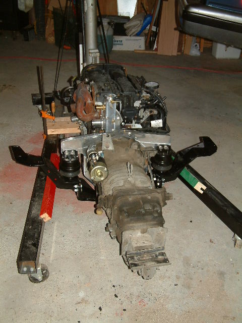

The two nicely colored blocks were left over from a wood project and were exactly the size needed. This arrangement allowed the assembly to roll on the hoist arms, clearing the floor by about one-half inch, leaving lots of room above as it went under the van:


For the actual raising of the engine to attach the mounts (the front mount that holds the transmission, and the two sides of the new black steel engine cradle), you'll have to use your imagination, since I didn't use the camera. Essentially, it involved a large number of trips under the van, back out to the hoist jack to slightly raise or lower the engine, work the engine slightly forward or rearward, back under to work the CV joints into position, more fiddling, etc. The front mount gets loosely attached first, then the rear of the engine is raised until the CV joints can be attached with a couple of bolts on both sides, then final raising, fixing bolts (one on each side has to be drilled, in addition to two on each side that fit pre-made holes). It was all complete on Monday afternoon, at which point I took a break to give my arms a rest.

Tuesday (yesterday) I added the exhaust system (kit SK-E, see part of it above), and went through most of the intake system (SK-I), stopping at the point where I need to install the new fuel lines. These should arrive tomorrow (Thursday), so today I will probably, if I have time, remove the rear part of the shift linkage and install the new shift boots and bushing. Here's the engine side of the modified intake system, showing the milled adapter that holds the throttle body, which in turn is attached to a LONG ribbed intake hose that goes all the way around to the passenger-side taillight area.

For those who may have wondered, the white marks on the cam cover are from battery acid that apparently squirted out of the battery when it got crushed in the accident that totalled the Focus that the engine came from . . .
Back to non-Vanagon work for awhile.
Friday, January 6, 2012
One step at a time
Well, the starter was in. I picked it up late in the morning, and got back around noon. Trembling with anticipation, I lifted it out of the box, and to my delight, found this:

And they mean IN THE BELL HOUSING, in a hole which is open on both ends when the transmission is off, but deep inside a blind hole when it's attached. Of course, you can extract and replace the bushing while the transmission is attached to the engine, using special tools VW9999xx and VW6666bs, etc. I, of course, don't have these tools, and couldn't purchase them to use just one time. Do I really need to replace this bushing? The message is pretty grim, of course - what do they care how hard it is to replace? The existing bushing looked, as far as I could see, okay. I thought about it awhile, then decided that I'd gone this far, no good reason to jeopardize the new starter I'd paid so much for. So, the alternative is to remove the transmission, again, and drift out the old bushing from the back of the bell housing towards the inside. Here's the old bushing after I pulled the trans (the shiny thing in the center is the bushing):

Doesn't look in bad shape . . . But I pushed it out with a drift, and put the new bushing in, using an almost equal-diameter bolt as a driver. No problem, nice and neat:

And, best of all, the old bushing really WAS in bad shape:

There are stress cracks, too, that don't show up in this low-res pic. Plus, it was a very loose fit on the new starter drive shaft. So, I felt better about deciding to pull the trans. I felt great when I was able to re-fit the transmission, all by myself, in almost half the time it took the last round. While this was satisfying, I really don't want to have a third opportunity to improve my skills with this.
Tomorrow: the whole thing goes under the van.
Waiting on the starter
We've connected the trans to the new engine:


This turned out to be relatively simple, since the engine hoist had an optional adjustable leveling accessory that could be cranked back and forth to adjust the front/back angle of the engine. After lining up the engine to the transmission (blocked level on a handcart), I had Joan hold the engine steady while I moved the trans onto the engine studs by pushing on the cart. The fit of the bell housing wasn't as tight as I had feared, and now we wait for the replacement starter, due today (Friday):

While it looks bad, it seems fully functional. However, I'd have to take it apart to see how badly worn the brushes are after 21 years, and since its location is MUCH easier to reach with the transmission out than when it's in, I think a preventive replacement is a good idea.
I've measured the clearance below the current height of the back of the van, and have more than enough room to get the engine/transmission back underneath, but it will require some thought whether to try to push it under on the arms of the transmission hoist (as the old engine was when it came out), or knock together some sort of slide to push it on.
In the meantime, I've completed the modification of the stock airbox, and installed the new chipset into the salvaged engine control computer. Also, we have on order three new rubber boots and one new bushing for the shift linkage, since the old boots are nothing more than a broken series of rubber rings. Replacing them will allow a newly-greased linkage to work better, I hope.
Sunday, January 1, 2012
It's a New Year, but the same old Vanagon
The blue bus has seen many New Years. Anyway, I have ordered the new starter (. . . gulp . . . $150), but after the alternator fiasco and the one-foot-in-the-grave release bearing it seems the only rational thing to do. I hope this is the last financial hurdle we have to leap before this project is done.
I have removed the old starter, which is worth $20 as a core trade-in on the new (actually, rebuilt) starter. The new starter is due in, at latest, next Friday (1/6/!2012!). So in the meantime, I will mate the trans and engine, drag both of these underneath the van, and ready them for installation. I will also have to separate the power steering pump from its hoses. The Bostig instructions and video have this step as part of removing the engine. I decided, instead, to un-bolt the PS pump and wire it to the sidewall until after I got the engine out. I had two reasons for this: 1) No matter how it's done, disconnecting the PS pump will result in spilled oil, which will be easier to catch and clean up if it's done after the engine is out of the way; 2) I can hold the PS pump higher than its reservoir tank as I disconnect the hoses, and then cap the hoses and reduce the amount of leakage. Clever, huh? I'll let you know if it actually works better that way.
I have also decided to renew the boots on the transmission shaft. These are inexpensive (comparatively!), and combined with a cleaning and re-lubricating of the shift linkage, should improve the feel of the shift linkage. It's probably the last time I'll have access to new parts for this stuff, too. The digrams in the Bentley manual for VW don't show clearly how the shift linkage comes apart, but I perceive a couple of likely methods, and unless one of them destroys the linkage, you'll only hear about how well it went.
Fly-in-the-ointment time, though. After many misleading days of moderate temperatures, it's now forecast to be in the upper 20's (F, for my Canadian friends) Monday through Wednesday. Except for nights, which are set to be 13 on Tuesday morning, 10 on Wednesday. I may have a hard time warming up the work area.
Subscribe to:
Posts (Atom)